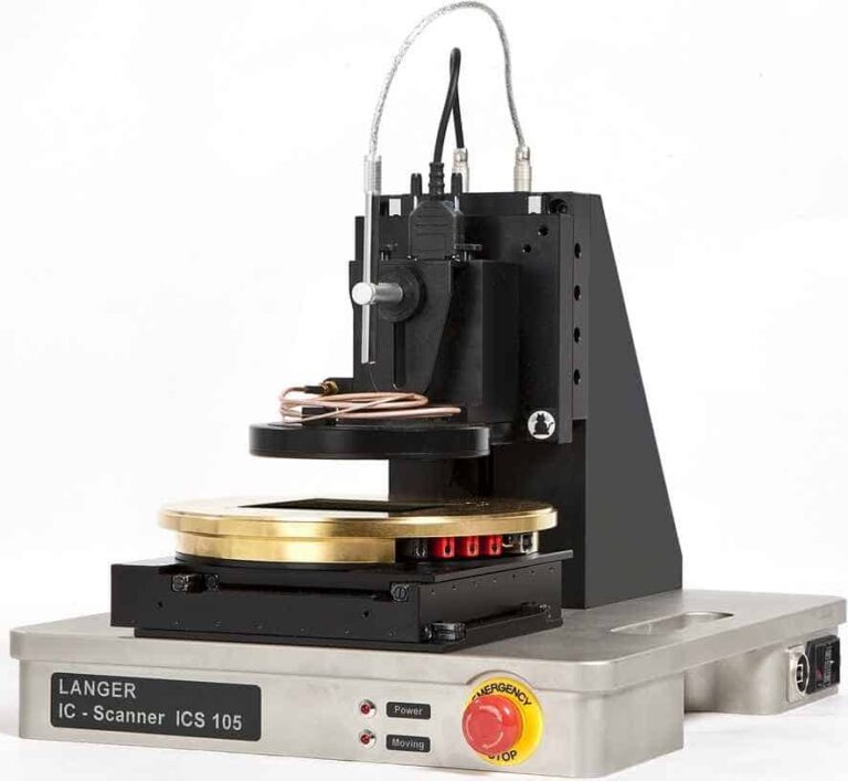

IC Scanner 4-Axis Positioning System
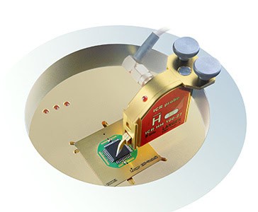
The ICS 105 IC scanner allows for measurements of high-frequency near fields above ICs. Depending on the used ICR near-field microprobe magnetic or electric fields can be measured with a measuring resolution of 50 to 100 µm. The probe can also be automatically rotated to determine the magnetic field’s direction.
Optionally the ICS 105 scanner can be used for measurements above small assemblies in combination with UH-DUT universal holder and SH 01 probe holder.
The IC scanner can be set up for ESD or EFT immunity tests on ICs in a few simple steps.
| Supply voltage | 110 / 230 V |
| Interface | USB |
| Max. traverse range | (50 x 50 x 50) mm; α-Rotation ±180° |
| Min. step size | (10 x 10 x 10) µm; α-Rotation 1° |
| Positioning speed | (10 x 10 x 5) mm/s; α-Rotation 90°/s |
| Weight | 23 kg |
| Sizes (L x W x H) | (350 x 400 x 420) mm |
| 3D scan |  |
| Surface scan |  |