Langer EMV-Technik

PCB Immunity, PCB Emission, IC Test, IC Security & Positioning Systems

PCB Emission

About Langer EMV-Technik

Langer EMV-Technik is in the forefront of research, development, and production in the field of EMC. Through EMC experimental seminars and EMC workshops. Langer EMV-Technik offers comprehensive knowledge to their customers.

Langer EMV-Technik interference emission and interference immunity EMC measurement technology as well as the IC test system are used mainly in the development stage and are in worldwide demand.

Developers and designers gain new perspectives and more efficient working strategies for module- and IC developments with the EMC know how and measurement technology of Langer EMV-Technik GmbH.

The individual pre-compliance consulting services provided by Langer EMV-Technik GmbH help developers and designers quickly find solutions to complex EMC problems in IC, device, and module development.

Langer EMV-Technik make both our comprehensive EMC expertise and research results available to their customers via practical experimental EMC seminars and in-house events .

PCB Emission

Measurement Technology for the Development Stage

ESA1 set

Emission Development System

The ESA1 is a system of EMC tools for measuring the interference of assemblies and devices. The CS-ESA software allows the developer to quickly and comprehensively suppress interference affecting the DUT. Interference measurements taken during the development stage with ESA1 are proportional to the results from far-field measurements or from measurements with artificial networks. With the ESA1 tools disturbance sources can be localized, effects can be detected, and EMC measures individually determined. The effects of improvements implemented by ESA1 are proportional to the results from far-field measurements. ESA1 is designed for use at the developer’s working place.

HFW 21 set

RF Current Transformer 100 kHz up to 1 GHz

The RF-current transformer measures high-frequency currents at the DUT’s lines. For reproducible measurements a metallic ground plane is needed as a reference plane. The small-scale measurement set-up at the developer’s workspace allows for fast analysis of EMC measuring effects.

The HFW 21 allows for the separate measurement of common-mode currents and differential-mode currents.

Scope of delivery
Technical parameters
Frequency range100 kHz – 1 GHz
Weight400 g

Z23-1 set

Shielding Tent (900 x 500x 400) mm
Scope of delivery
Technical parameters
Attenuated shielding45 dB – 50 dB / 30 MHz – 1 GHz
Weight12 kg
Sizes (L x W x H)(900 x 500 x 400) mm
Shielding attenuationShielding attenuation

NNB 21 set

Line Impedance Stabilisation Network
Scope of delivery
Technical parameters
Frequency range100 kHz – 1 GHz
DC resistance< 20 mΩ
Internal attenuation10 dB
Measuring channels2
Continuous power rating 
Current10 A
Dielectric strength50 V
Weight400 g

Near-Field Probes

LF, Passive

100 kHz up to 50 MHz


The LF family consists of seven magnetic-field probes, four of which are included in our LF1 probe set. We are happy to create customized sets upon request.

RF, Passive

30 MHz up to 3 GHz


The RF family consists of nine magnetic field probes and six E-field probes, which are available in sets. These sets are optimized for different measurement tasks. We are happy to create customized sets upon request.

XF, Passive

30 MHz up to 6 GHz


The XF family consists of four magnetic-field probes and three E-field probes. The XF1 set (four magnetic-field probes and one E-field probe) as well as customized sets are available.

SX, Passive

1GHz up to 20 GHz
 

The SX family consists of three H-field probes and one E-field probe. The SX1 set (two H-field probes and one E-field probe) and the SX-R 20-1 set are available.

HR, Passive

Up to 40 GHz


The HR family consists of an H-field probe and an E-field probe for the measurement of high-frequency RF fields up to 40 GHz during development.

MFA, Active

1MHz up to 6 GHz


The MFA family consists of four active magnetic field probes. The MFA 01 includes three magnetic field probes. The MFA 02 set consists of two magnetic field probes for low frequency measurements.

CM-SHP

Customized Shapes


Langer EMV-Technik GmbH also manufactures special shapes of near-field probes according to customer requirements. Here are some examples.

Individual Characterization

Product Characterization


The characterization service for our near-field probes includes: The determination of the transfer function of the near-field probe on a special microstrip line that guarantees a defined field distribution. Furthermore, correction values are generated from this measurement data to more accurately

Fields of application

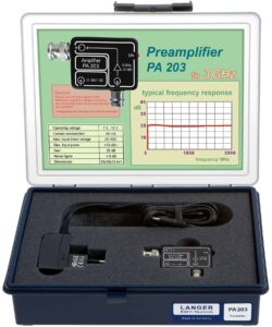
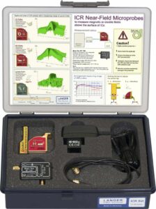
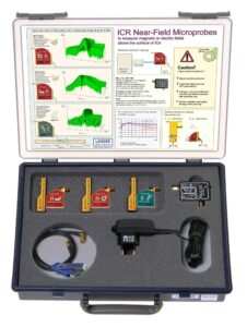
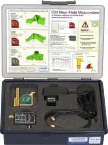
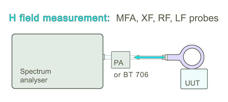
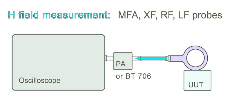
RF field measurement for E- and H-field with near-field probes and a spectrum analyzer or an oscilloscope.

Correcting Characteristic Curves of Magnetic Field Probes

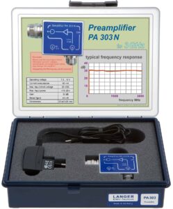
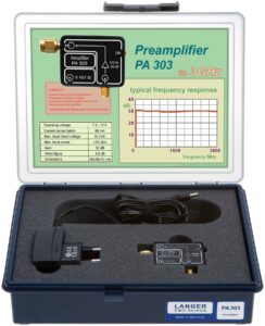
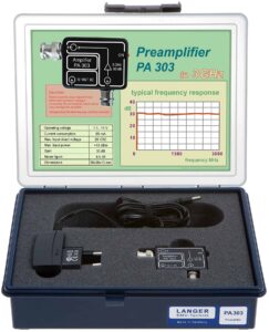
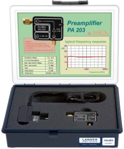
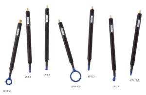
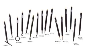
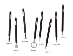
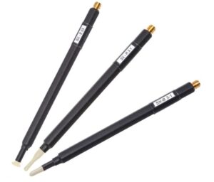
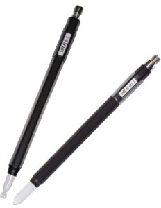
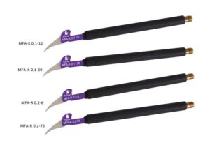
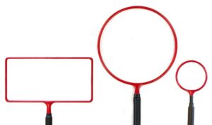
RF-type probes from Langer EMV-Technik GmbH

Magnetic field strength and current determination

The following paragraph explains how magnetic field strength and underlying currents are calculated from the results of near-field measurements.

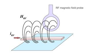
A magnetic field probe emits a Uprobe voltage signal output which is dispersed into a spectrum by a spectrum analyzer. A correction factor KH is defined which describes the relationship between the voltage signal and the associated magnetic field HRF. The magnetic field HRF is linked with a current IRF. Another correction factor can, thus, be defined based on the current IRF.

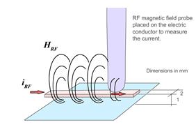
Magnetic field correction:

The magnetic field strength HRF in the coil of the magnetic field probe can be calculated from the voltage output signal of the Uprobe magnetic field probe by means of the correction characteristic. The correction factor of the magnetic field probe is independent of the measurement geometry in each individual application, i.e. the probe can be guided at an arbitrary distance and angle relative to the electric conductor without any correction error (Figure 2). The result is the average magnetic field that is enclosed by the probe coil (Figure 1).

Homogenous H field
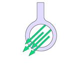
Figure 1 Field strength distribution in the probe coil
Figure 2 General application layout

Use of the correction factor KH in the adapted quantity equation:

Example of how the quantity equation is used, Figure 3:

Figure 3 Example of how the magnetic field correction characteristic is used

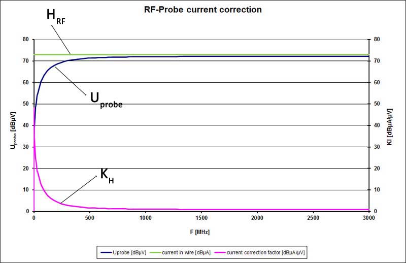
In Figure 3 the magnetic field probe was located in a magnetic field that is constant over the frequency range. Due to the coupling factor the voltage which is induced in the probe depends on the frequency. The coupling factor intermediates between the measured voltage Uprobe and the mean magnetic field strength. The existing magnetic field strength is obtained if the correction factor is added to the measured voltage Uprobe (logarithmized quantity equation).

The mean magnetic field strength HRF can be determined from the measured curve Uprobe and the correction characteristic KH using the quantity equation. The result is shown in Figure 3.

Current correction:

There is a consistent physical correlation between the magnetic field HRF and the current IRF which depends on the geometry of the current conductor layout. The given correction factor KI thus refers to a defined reference set-up.

The determined current values Icorr are only correct if the geometric parameters coincide with the reference set-up when the probes are used. If there are deviations from this set-up, the current values Icorr will also deviate. The calculated current value Icorr can only be used as an orientation value.

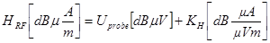
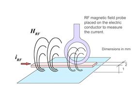
The reference set-up has the following geometric parameters (Figures 4 and 5):

  • Width of the conductor run 2 mm
  • Height of the conductor run above the ground system 1 mm
  • Probe placed on the conductor run
Figure 4 Measurement set-up for the RF-R 400-1, RF-R 50-1. RF-R 3-2,RF-R 0.3-3 near-field probes
Figure 5 Measurement set-up for the RF-B 3-2, RF-B 0.3-3, RF-K 7-4, RF-U 2.5-2, RF-U 5-2 near-field probes

Use of the correction factor KI in the adapted quantity equation:

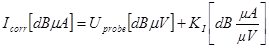
The example is based on a current that is constant over the frequency range (Figure 6). This current induces a voltage in the magnetic field probe which is measured as Uprobe by the spectrum analyzer. The frequency-dependent correction factor is added (logarithmically) from the voltage waveform to obtain the current in the conductor. Icorr is the current in dBµA which flows in the reference set-up.

Figure 6) Current correction example (Current in dBµA [yellow])

Preamplifier

PA 2522 set

Preamplifier 10 MHz up to 22 GHz

The PA 2522 preamplifier was designed for the amplification of measuring signals, e.g. weak signals of near-field probes with high resolution. The PA 2522 is to be used with the 50 ohm input of a spectrum analyzer or an oscilloscope and is powered by the plug-in power supply. With the correct cable …

PA 3010 set

Preamplifier 10 MHz up to 10 GHz

The PA 3010 preamplifier was designed for the amplification of measuring signals, e.g. weak signals of near-field probes with high resolution. The PA 3010 is to be used with the 50 ohm input of a spectrum analyzer or an oscilloscope and is powered by the plug-in power supply. With the correct cable …

PA 306 SMA set

Preamplifier 100 kHz up to 6 GHz

The PA 306 SMA serves for amplifying measurement signals, for example weak signals from high-resolution near-field probes. The PA 306 is connected to the 50 Ω input of a spectrum analyzer or oscilloscope and supplied via the plug-in power supply unit included in delivery.

PA 303 N set

Preamplifier 100 kHz up to 3 GHz

The PA 303 N preamplifier was designed for the amplification of measuring signals, e.g. weak signals of near-field probes with high resolution. The PA 303 N is to be used with the 50 ohm input of a spectrum analyzer or an oscilloscope and is powered by the wall-plug transformer. With the correct cab…

PA 303 SMA set

Preamplifier 100 kHz up to 3 GHz

The PA 303 SMA preamplifier is designed for the amplification of measuring signals, e.g. weak signals of near-field probes with high resolution. The PA 303 is connected to the 50 ohm input of a spectrum analyzer or an oscilloscope and is powered by the wall-plug transformer. With the correct cable a…

PA 303 BNC set

Preamplifier 100 kHz up to 3 GHz

The PA 303 BNC preamplifier is designed for the amplification of measuring signals, e.g. weak signals of near-field probes with high resolution. The PA 303 is connected to the 50 ohm input of a spectrum analyzer or an oscilloscope and is powered by the wall-plug transformer. With the correct cable a…

PA 203 SMA set

Preamplifier 100 kHz up to 3 GHz

The PA 203 preamplifier is designed for the amplification of measuring signals, e.g. weak signals of near-field probes with high resolution. The PA 203 is connected to the 50 ohm input of a spectrum analyzer or an oscilloscope and is powered by the wall-plug transformer. With the correct cable, a ne…

PA 203 BNC set

Preamplifier 100 kHz up to 3 GHz

The PA 203 BNC preamplifier is designed for the amplification of measuring signals, e.g. weak signals of near-field probes with high resolution. The PA 203 is connected to the 50 ohm input of a spectrum analyzer or an oscilloscope and is supplied by the wall-plug transformer. With the correct cable…

Near-Field Microprobes

Near-Field Microprobe Sets ICR HH H Field


The ICR HH set contains one ICR near-field microprobe for magnetic field measurement. The measuring coil is horizontal in the probe head. The ICR probes are operated with a positioning system (Langer Scanner).

Near-Field Microprobe Sets ICR HV H Field


The ICR HV set contains one ICR near-field microprobe for magnetic field measurement. The measuring coil is vertical in the probe head. The ICR probes are operated with a positioning system (Langer Scanner).

ICR 03 set, Near-Field Micro probes Set


The ICR 03 set contains three of our ICR near-field microprobes (magnetic or E field) of your choice. The probes are used to measure magnetic or electric near fields with extremely high resolution and sensitivity. Optimal is a distance of < 1 mm to the measuring object. The probe head is equipped wi…

ICR E150 set, Near-Field Microprobe E-field 7 MHz up to 3 GHz


The near-field microprobe is designed for a high-resolution measurement of electrical near fields. With the ICR E probe the following measurements can be performed: – Surface Scan via IC according to IEC 61967-3 – Volumenscan via IC – Pin Scan The measuring electrode at the ICR RF probe head is hori…

Want help or have questions ?

Contact us
Scroll to Top